Before the surface induction heat treatment of automobile wheel products, the design of the inductor is very important. The quality of the induction heating coil directly affects the debugging and processing of the product and has a great impact on the quenching quality of the product. For the induction heat treatment of a certain product, analyze and discuss the design of the inductor to the completion of product commissioning.
Overview
Metals can be heated in an inductor, mainly relying on the phenomenon of electromagnetic induction. The essence of electromagnetic induction is: an alternating magnetic field causes an alternating electric field, and an alternating electric field causes an alternating magnetic field. When an alternating current passes through a conductor, the current density on the surface of the conductor is relatively large, while the current density inside the conductor is relatively small. This phenomenon is the skin effect, also known as the skin effect or surface effect. In addition, there are proximity effects and ring effects, which are very important for induction heat treatment. Induction heat treatment has a short heating time, less oxide skin, small deformation, energy saving, and environmental protection, and it is easy to realize mechanization and automation. Therefore, it is widely used in automobile manufacturing, tractors, construction machinery, heavy machinery, bearing industry, railway and metallurgy and other industries. The trend is very good.
The author has been engaged in the induction hardening of automobile wheel hubs for nearly 10 years. The process flow of the induction heat treatment of the outer flange and inner flange is analyzed and sorted out below for reference and discussion by colleagues.
Product Drawing Analysis
The structures of the outer flange and the inner flange are shown in Figure 1 and Figure 2 respectively.
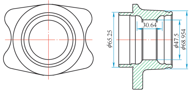
Figure 1 Outer flange structure
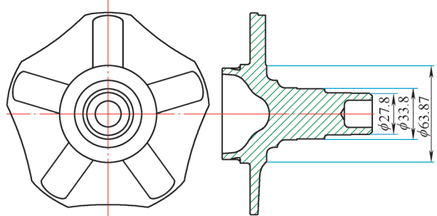
Figure 2 Inner flange structure
1. Critical dimensions
Outer flange (inner hole): product wall thickness, inner diameter, height, groove spacing, base circle size, overall structure, etc.
The groove spacing of this product is 30.64mm, the base circle diameter is 65.25mm, the caliber wall thickness is 10mm, and the length of the quenching area is 40mm. Inner flange (outer circle): the shaft diameter of the main channel of the product, shaft height, base circle size, and overall structure, etc. The product is a solid shaft with the main channel diameter of 33.8mm, a shaft height of 71.1mm, a base circle diameter of 60mm, and a quenching area length of 52mm.
2. Technical requirements
Heat treatment technical requirements are shown in Figure 3 and Figure 4.
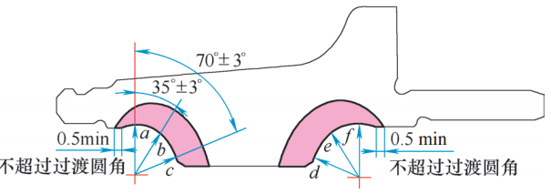
Figure 3 Outer flange
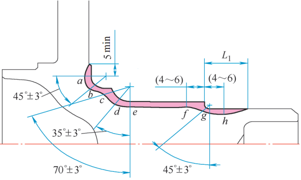
Figure 4 Inner flange
(1) Technical requirements for quenching and tempering of inner and outer flanges
The quenching surface hardness is 62-65HRC, and the tempering surface hardness is 59-63HRC. The metallographic structure is martensite 4~6.
(2) Technical requirements for outer flange detection
Detected in the direction of the pattern angle, a, f point Ds = 1.9 ~ 3.2mm; b, e point Ds = 2.2 ~ 3.7mm; c, d point Ds ≥ 2.4mm.
(3) Technical requirements for inner flange detection
Detect a, b, e, h point Ds=1.9~3.7mm in the pattern angle direction; d point Ds=2.2~3.7mm; g point Ds≥1.5mm; c point Ds≥2.4mm; f point Ds=2~6mm.
3. Construct the product sensor pattern
According to the above dimensional data and product-related technical requirements, measure the total height of the sensor and the size of the effective circle, draw the design pattern of the sensor, modify it according to the actual situation, and finally determine the shape of the induction hardening coil.
4. Determine the material and size of the induction hardening coil
The induction hardening coil is composed of an effective coil, a conductive plate, a contact plate, and accessories, and is made of various materials.
(1) Conductive contact plate, effective ring, and conductive plate. Made of T2 pure copper and brazed with brass electrodes.
(2) The water inlet and outlet pipes are round copper pipes with an outer diameter of 12mm and a wall thickness of 2mm; square copper pipes of 14mm×14mm×2mm.
(3) Effective circle. The square copper pipe of the outer flange is 8mm×10mm×1.5mm; the square copper pipe of the inner flange is 12mm×15mm×2mm.
1. Induction hardening coil design pattern
The induction hardening coil design is shown in Figure 5.
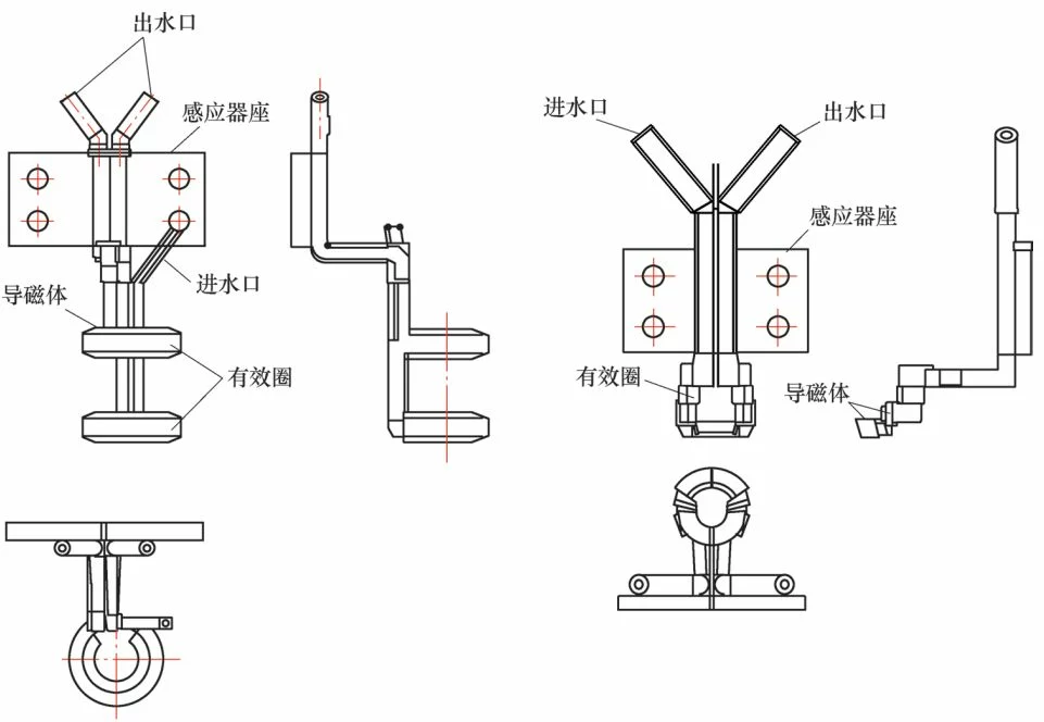
Figure 5 induction hardening coil design pattern
(1) According to the product structure, design, measure and draw the sensor pattern, and mark the name of each component.
(2) Contact plate. As shown in Figure 6.
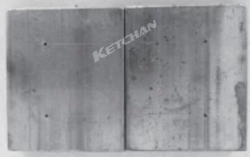
Figure 6 Connect plate
The contact plate should ensure that it can be connected reliably, tightly, and firmly with the quenching transformer. The thickness of the contact plate should be >1.57d (d is the current penetration depth), but <12mm, and the thickness of the plate here should be 10mm.
The board width varies according to the power of the sensor. Generally, it is selected within the range of 60-190mm, and the upper limit is selected when the power is large. Here, the board width is selected as 60mm, and the board length is selected as 70mm.
The punching diameter of the pressing bolt on the contact plate is 15mm, and there are 4 bolt holes in total, and the bolts can use M12. It should be noted that the positions of the four fixing holes must be measured well, otherwise, the connection with the transformer will not be in place.
In addition, the power on the inductor is distributed along the length of the conductor, so the conductive plate should be wide rather than narrow.
(3) The effective circle design of the sensor. In order to ensure the quality of sensor production, some necessary molds must be prepared.
The production of the effective ring requires winding the mandrel mold (see Figure 7), and the copper tube is wound on the mandrel after annealing. The diameter of the mandrel should be a little smaller than that of the inductor after winding the finished product.
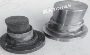
Figure 7 Winding mandrel mold
Take the outer flange as an example: the width of the copper tube in the effective circle of the induction coil is 10mm, the diameter of the shoulder of the product is 47.5mm, and the diameter of the mandrel can be 35mm. The inner flange product also chooses the mandrel winding, in which the induction coil at the R corner of the winding product can be selected, the diameter of the mandrel can be 63mm, and this section of the induction coil should be processed into a slope with a certain angle in order to improve the quenching efficiency at the R corner. . The effective rings of other parts are wound according to the size of the drawing.
(4) The parameters are determined. The inductor is divided into outer circle quenching and inner hole quenching. The height difference between the effective circle and the workpiece and the gap between the effective circle and the workpiece should be determined according to the frequency of the on-site quenching equipment, as shown in Table 1 to Table 4.
Table 1 Height difference between the effective ring and the workpiece when the inner hole is heated
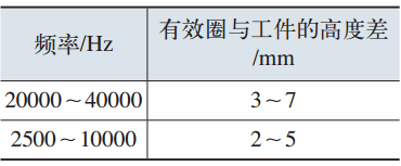
Table 2 The gap between the effective ring and the workpiece when the inner hole is heated
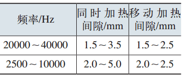
Table 3 Height difference between the effective ring and the workpiece when the outer circle is heated at the same time
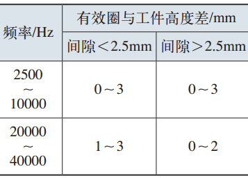
Table 4 The gap between the effective ring and the workpiece when the outer circle is heated
Product Debugging and Acceptance
1. Installation
(1) Select a hardening machine tool to install sensors and auxiliary devices, as shown in Figure 16.
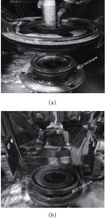
Figure 16 induction coil and auxiliary device installation
Installation Precautions:
- Be sure to pay attention to the closeness of the connection between the induction coil and the transformer when installing the tooling, and the bolts must be locked.
- Pay attention to the verticality of the effective circle and the product when installing the sensor, the sensor cannot be, tilted, otherwise it will affect the quenching quality of the product.
- The outer flange needs to be installed with a product pressure sleeve as a heat-absorbing device, which is more stable than some auxiliary external spraying methods.
- Check the circular runout of the workpiece when it is rotated on the fixture. General tooling circular runout ≤ 0.3mm.
(2)The power matching of induction hardening equipment is 250kW/8~30kHz.
(3) Adjust the hardening equipment, determine the appropriate hardening process, and meet the hardening technical requirements of the product.
Outer flange products: power input ratio 98%, heating time 7.4s, cooling time 14s, quenching liquid concentration 1.5%~2.5%.
Inner flange products: power input ratio 98%, heating time 7.7s, cooling time 20s, quenching liquid concentration 1.5%~2.5%.
Shanghai Houghton water-soluble quenching liquid was used, and its concentration was detected by a refractometer.
2. Adjustment of cooling device
(1) Guarantee the cooling pressure, here the cooling pressure of the quenching liquid is 0.25-0.4MPa, and the cooling pressure of the sensor is 0.5-0.8MPa.
(2) The position of the cooling device is adjusted so that the cooling water cannot be blocked or blocked.
(3) The cooling water has two parts, one is the quenching liquid, and the other is the system cooling water, and heat exchangers are generally used for temperature cooling.
The temperature of the quenching liquid is generally not higher than 35°C. If the temperature is too high, it will cause insufficient cooling, resulting in quality problems of the product. The temperature of cooling water in the system is the soft water for cooling electrical appliances. This temperature is generally controlled at 30°C and must not be lower than room temperature. Otherwise, water droplets will condense on the surface of the cooled electrical appliances and easily damage the electrical appliances.
3. Product inspection method
Heat treatment product inspection requires wire cutting and metallographic specimen pre-grinding machines.
4. Product tempering process
The tempering of induction-hardened workpieces includes self-tempering, induction tempering, and furnace tempering. The products here are tempered in the furnace.
The tempering temperature is determined according to the technical requirements of the workpiece. Generally, when the hardness requirement is above 52HRC, the tempering temperature is 180-200°C and the tempering time is 1.5h; when the hardness requirement is above 56HRC, the tempering temperature can be 160°C and the tempering time is 1.5h.
The tempering process of this product is finally determined as a tempering temperature of 165°C and a tempering time of 2.5 hours.
5. Inspection
Figure 17 and Figure 18 are product samples that have been successfully debugged.
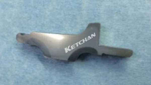
Figure 17 Quenching sample of the outer flange
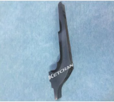
Figure 18 Quenching sample of the inner flange
Table 5 and Table 6 are the inspection data of the first piece of debugging products
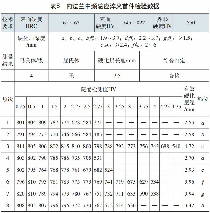
Tested by Vickers hardness tester, the product surface hardness and effective hardened layer depth all meet the technical requirements. The heat treatment of this product has been successfully completed from tooling sensor design to product debugging.
Epilogue
The structure, shape, and size of the induction coils are the core issues of induction hardening technology, which have a direct impact on the induction hardening quality, production efficiency, and energy consumption of parts. Therefore, a suitable induction heating coil is an important way to make induction hardening obtain high quality, high efficiency, and energy saving.