The principle of dual-frequency induction heating
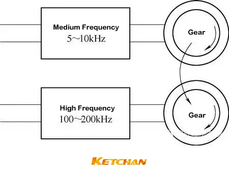
Conventional (traditional) dual-frequency induction hardening is that two frequency power supplies are applied to two inductors respectively, and the gear needs to be preheated from the low-frequency inductor and quickly moved to another high-frequency inductor for heating and quenching, as shown in Figure 1. Dual-frequency induction hardening uses low-frequency heating to diffuse heat energy to the inside, and finally high-frequency heating to the surface, that is, the feature of “low frequency tends to the inside, high frequency tends to the surface”.
Figure 1 Schematic diagram of conventional gear dual frequency quenching
Dual-frequency induction hardening is an induction heating and quenching method to increase the depth of the hardened layer and make the hardness distribution more reasonable. That is to say, the hardened layer distributed along the tooth profile can be obtained by using the medium frequency-high frequency sequential heating method, and the gear heat treatment distortion is small.
For example, for a gear with a modulus of 4mm, use medium frequency current to heat (2.5~3s) the tooth groove and the tooth side near the tooth root, and then use 250kHz high frequency current to heat (0.6~0.7s) the tooth top and the tooth near the tooth top side, then quenched.
When Guangzhou Automobile Group Co., Ltd. performs dual-frequency induction heating and quenching on gears made of 45 steel and modulus 3, a hardened layer uniformly distributed along the tooth profile can be obtained. When the hardened layer is 0.8mm, the best Excellent bending fatigue performance, which is basically equivalent to that of SCM420 (equivalent to 20CrMo steel) carburized gear fatigue performance, and the fatigue limit can reach 1450MPa.
Dual-frequency induction heating process and effect
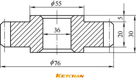
Nihon Electric Industrial Co., Ltd. has tested the gear double-frequency quenching method and can obtain smaller distortion than the gear single-frequency quenching method and carburizing quenching method. The involute cylindrical gear (see Figure 2) has a modulus of 2mm and a full tooth height of 4.7. mm, the number of teeth is 36, and the material is S45C steel (equivalent to 45 steel). The tooth surface is finished by shaving, and the preheat treatment is for tempering.
Figure 2 Test gear shape
The dual-frequency induction hardening method is shown in the picture below. First put the gear on the fixture, and then rotate with the central axis at high speed, at the same time, the induction power supply (1) sends a current of f=3000Hz, and enters the inductor (A). ) for preheating. When the gear reaches the optimum temperature, the power supply (1) is cut off, and the gear quickly falls into the quenching and heating inductor (B), and at the same time, the high-frequency power supply (2) starts to transmit power, the frequency f=140kHz, and the tooth surface of the gear Fast quenching and heating of the tooth top, when the tooth surface reaches the quenching temperature, cut off the high-frequency power supply, reduce the rotation speed of the gear, and at the same time spray cooling water from the quenching water jacket to rapidly cool the tooth surface, tooth top, and tooth root. A hardened layer distributed along the profile of the tooth is obtained.
The dual-frequency induction hardening method
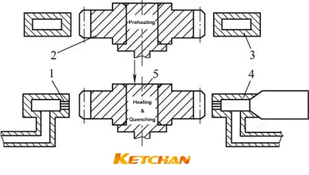
1. Water spray hole 2. Gear 3. Preheating sensor (A) 4. High frequency heating sensor (B) + quenching water jacket 5. Fixture
Table 1: shows the process parameters of three heat treatments for gears.
| The main process parameters of double frequency, single frequency hardening and carburizing hardening | ||
|---|---|---|
| Dual-frequency hardening process parameters | Single-frequency hardening process parameters | Carburizing hardening process parameters |
| Preheating power 100kW | Heating power 90kW | Carburizing 950℃ |
| Preheating frequency 3kHz | Frequency 90kHz | 950 ℃ and heat preservation 2.5h |
| Preheating time 3.65s | Heating time 3.8s | Precooling down to 850℃ |
| Air cooling time 3.85s | Preheating time 0s | 850℃ for 20min |
| High frequency input power 900kW | ||
| High frequency frequency 140kHz | Water spray time 15s | Quenching cooling medium - oil |
| Heating time 0.14s | Heating time 0.14s | Tempering temperature 180℃ |
| Water spraying time 10s | / | Tempering time 2h |
| Water spray flow rate 100L/min | / | Followed by air cooling |
The test results of gear distortion, residual compressive stress and profiling rate along the tooth profile after three processes are shown in Table 2. It can be seen from Table 2 that the heat treatment distortion of the gear after dual-frequency quenching is the smallest, the precision is the highest, and the residual compressive stress is the highest.
Table 2: Thermal distortion results after carburizing and quenching, single-frequency induction hardening and double-frequency induction hardening (μm)
| Thermal distortion results after carburizing and quenching, single-frequency induction hardening and double-frequency induction hardening (μm) | ||||
|---|---|---|---|---|
| Item | Carburizing Quenching + Tempering | Single Frequency Induction Hardening | Dual Frequency Induction Hardening | Notes |
| Average profile error | 4.26~4.8 | 2.2~3.3 | 3.1~308 | / |
| Tooth profile offset | 16 | 8.4 | 6.0 | / |
| Tooth runout | 5.867 | 3.103 | 2.198 | / |
| Average value of tooth direction error | 6.91 | 3.7~4.1 | 3.7~4.1 | / |
| Tooth error offset | 20 | 4.4 | 4.4 | / |
| Tooth runout | 7.51 | 1.855 | 1.584 | / |
| Middle of tooth root Residual stress/MPa | -27.7 | -51.3 | -778 | / |
| Tooth top hardened layer depth /mm | 0.87 | 4.69 | 1.54 | When the root hardened layer depth is 0.55mm |
| Hardened layer profiling rate (%) | 81.5 | 0.2 | 67.2 | / |