At present, there are many types of grooved quenched parts, such as camshaft opening grooves, differential housings, etc. However, the quality of quenching of grooved parts has not been guaranteed, and quenching is also very difficult. In this paper, the groove-type quenching inductor is improved in one form and two, and adjusted in the process debugging, so that the quenching effect is ideal and meets the requirements of various groove parts.
1. Discussion on quenching inductors for grooved parts
(1) Status of grooved quenching inductors
The inner side of the part slot is heated, especially when the inner side width is small, it is difficult to design the inductor. The inductor in Figure 1 utilizes the principle of proximity effect to heat the inner surface, with high efficiency. The active part of the inductor is the two conductive tubes in the middle. Since the current directions of the two tubes are in the same direction at any time, the current on the conductive tube is squeezed to the outside. Although no magnets are added to the two conducting tubes, they have quite high heating efficiency.
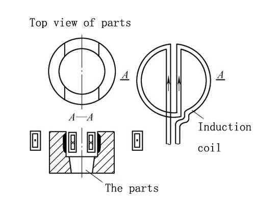
Figure 1 Two-wire heating industor inside the slot
(2) Design of quenching inductor with the small opening slot
Since the slot width is 9mm, two conductive tubes are used to make the inductor, the copper tubes used are very small, the fabrication is difficult, and the life of the inductor is very short. Therefore, it is improved, and a single copper tube is used for heating, and the proximity effect of induction heating is used for heating (see Figure 2).
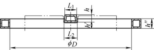
Figure 2 The improved industor structure
2. Application of groove quenching inductor
Afterwards, quenching tests were carried out with the camshaft grooves and the opening grooves of the differential case respectively.
(1) Quenching process test of camshaft open groove
Our company was entrusted by a camshaft manufacturer to quench the open groove of the camshaft. The width of the open groove is 9.3mm, the depth is 9mm, and the deformation of the groove width is less than or equal to 0.1mm (see Figure 3).
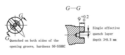
FIG. 3 Technical requirements for camshaft openings
The heating part of the inductor is first heated by a rectangular cross-section copper tube (see Figure 4), adjust the gap between the heating surface and the bottom surface of the opening slot, and use 50kW, 30kHz frequency for quenching, the quenching area is only about 4mm, which is far from meeting the technical requirements. The inductor structure needs to be improved.
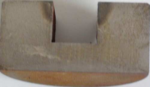
Fig. 4 Quenching sample block of copper tube with effective heating surface of rectangular section (30kHz)
The heating part of the inductor uses a trapezoidal section copper tube (see Figure 5), adjusts the gap between the heating surface and the bottom surface of the opening slot, and uses 30kHz, 50kW frequency for quenching, the quenching area is only 8mm, still does not meet the 9mm requirement, but it is very Approaching the technical requirements, it is necessary to adjust the process parameters at this time.
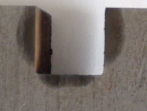
Figure 5 Quenching sample block of copper tube with trapezoidal section effective heating surface (30kHz
Try to use trapezoidal cross-section copper tube for the heating part of the inductor, adjust the gap between the heating surface and the bottom surface of the open groove, and use 5.8kHz frequency, 90kW short-time heating for quenching, the depth and hardness of the hardened layer on both sides of the entire open groove meet the technical requirements, the opening There is also a hardened layer on the bottom surface of the groove and at right angles (see Figure 6), and the deformation is also small (see the attached table), and the customer is very satisfied.
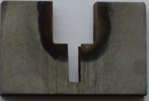
Figure 6. Trapezoidal section effective heating surface copper tube quenching sample (5.8kHz)
(2) Process test of the opening slot of differential case
Our company was commissioned by an automobile manufacturer to quench the connecting groove of the differential case (see Figure 7). The groove width is 18.5mm and the depth is 9mm. The 8 grooves are evenly distributed on the Φ120 and Φ75 rings. The technical requirement is forging After quenching and tempering treatment 90~230HBW, the dotted line part is induction hardened, the surface hardness is 53~59HRC, Ds=2~3mm.
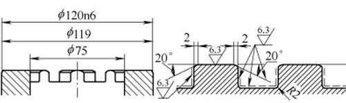
Figure 7 Technical requirements for the opening slot of the differential case
Since the quenching effect of the trapezoidal cross-section inductor is ideal in the front, this inductor structure is also used in the later tests. Use 5.8kHz, 98kW for heating and quenching, the gap between the inductor and the bottom surface of the tank is 0.5~1mm, and heating for 5.2s (note: add an auxiliary cooling system to prevent tempering near the quenching area of the open tank). Check that there is no hardened layer at the R2mm fillet (see Figure 8). The position of the sensor and the process parameters need to be corrected.
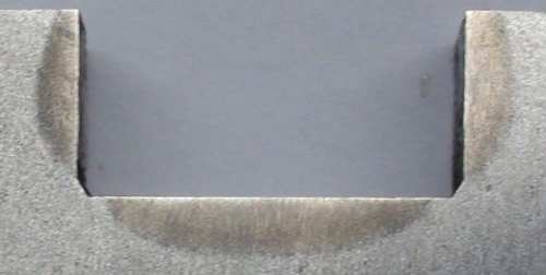
Figure 8 The first quenched sample of the differential case
According to the above test, the following corrections are made: increase the bottom edge gap to 1~1.5mm, use 5.8kHz, 98kW for heating and quenching, and extend the heating time to 6.5s for heating and quenching (Note: Add an auxiliary cooling system to prevent the quenching zone from being adjacent to the open slot tempered). Test results: The surface hardness on both sides of the groove is 55-56HRC, Ds=2mm; the surface hardness at R2mm is 55HRC, Ds=1.5mm; the surface hardness of the groove bottom surface is 56HRC, Ds=3mm (see Figure 9). The test results meet the technical requirements.
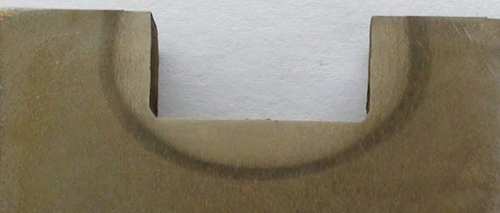
Figure 9 The second quenching sample of the differential case
3. Conclusion
The key points of quenching groove parts are as follows: the structure of the inductor and the effective heating surface structure, the gap between the inductor and the quenching part, and the matching of the quenching process parameters (frequency, power, heating time, etc.), and the anti-tempering cooling system near the quenching area.
In addition, the gap has a very obvious effect on the depth of the hardened layer of such parts, and it is difficult to ensure that the gap between the two sides of the sensor and the side of the opening groove is exactly the same, which makes the depth and shape of the hardened layer on both sides asymmetrical, so the accuracy of the positioning fixture appears to be very high. important.
Tags:case hardening, for Sale, induction hardening automobile components, induction hardening automotive parts, induction hardening cams, induction hardening CV joints, induction hardening CVJ, induction hardening differential cases, induction hardening grooves, induction hardening LJ outer, induction hardening machine, induction hardening machine tool, Induction hardening process, induction hardening service, induction hardening solutions, induction hardening steels, induction heater, induction heating, induction heating machine, inducton hardening machine, KETCHAN, KETCHAN Electronic, Manufacturers, price, Suppliers, tempering after induction hardening, Zhengzhou KETCHAN, Zhengzhou KETCHAN Electronic