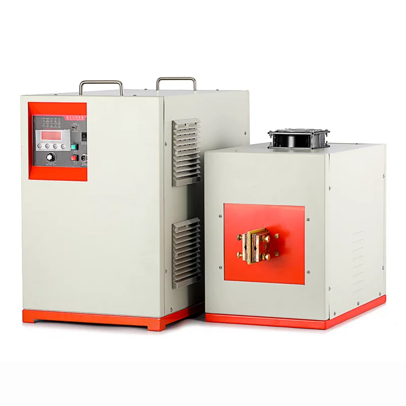
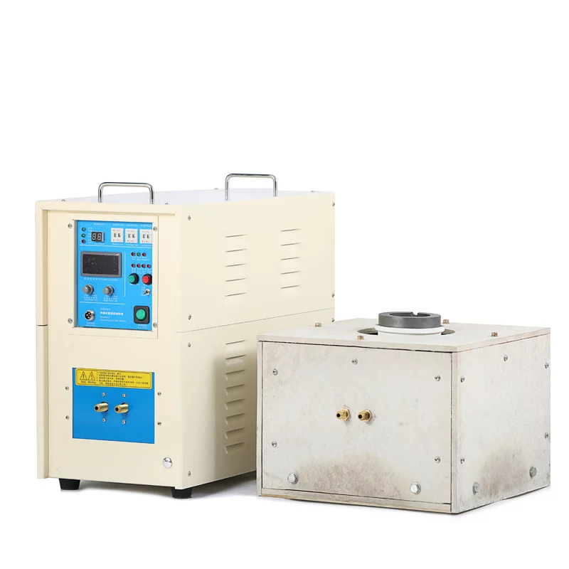
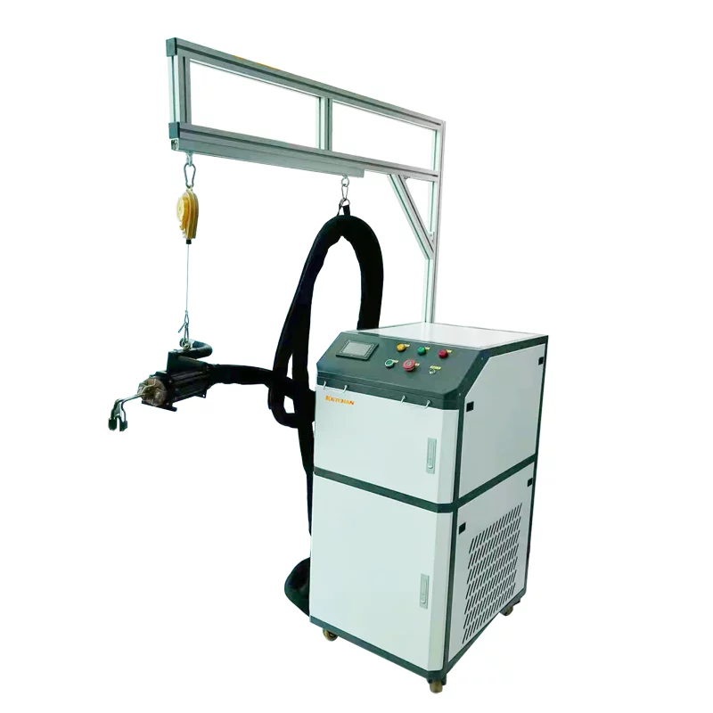
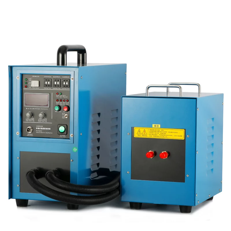
High carbon alloy-bearing steel (SUJ2) has its own characteristics of in-furnace heating and induction heating. In-furnace heating quenching has high production efficiency, and it is two-phase quenching for austenite and cementite. Induction heating quenching is more energy-saving, usually adopts high-temperature heating, hardening starts from austenite single-phase zone. In order to find out the optimal induction heating conditions, various tests were carried out and the properties of the heating products were compared with those in the furnace.
1. Test method
However, it is very difficult to measure the carbon content directly. Therefore, the area ratio of carbide is adopted instead of the carbon content of the solid solution. The test conditions are shown in Table 1 (the processing state is indicated on the sample in turn by heating temperature, carbide area ratio, and tempering conditions, such as “900-4-180”). The sample material is SUJ2 of the same batch, and the test size is 60 mm× 54 mm×15 mm. A high-frequency induction heater is used to heat the sample. Through the feedback control of the temperature in the central region of the test sample’s outer diameter, the sample temperature remained unchanged. After the completion of heating, quench with 70℃ cooling oil until the sample temperature drops to 100℃.
Table 1 Test conditions of induction heating
The basic characteristics of induction heating and heat treatment state are as follows: the carbide distribution of induction quenching products is shown in Figure 1, and the microstructure of different heat treatment conditions is different. The hardness, residual austenite content, and original austenite grain size after tempering are shown in Table 2.
FIG. 1 Carbide distribution
Table 2 Hardness, residual austenite content, and original austenite grain size after tempering
2. Selection of optimal heat treatment conditions
2.1 Size change rate test
The temperature was held at 230°C for 2h, and the size change rate after heating was measured, as shown in Table 3. The samples of the three carbide area ratios are all unqualified.
FIG. 3 Size change rate
2.2 Rated static load test
The test results are shown in Figure 2. The rated static load of products in the shaded area is lower than that of products heated in the furnace (risk factor is 5%). This means that the rated static load is reduced when heated at 1000℃.
FIG. 2 Rated static load
2.3 Static fracture strength test
The samples do not include those that have not passed the size change rate test and those heated at 1000℃ with a low static load rating. The static fracture strength test results are shown in Figure 3. The static fracture strength of products in the shaded area is lower than that of products heated in the furnace (risk factor is 1%).
FIG. 3 Static fracture strength
2.4 Shear fatigue strength test
FIG. 4 shows the results of the shear fatigue strength test, and the stress amplitude when the load cycle is 3 × 10⁹R is shown in FIG. 5.
FIG. 4 Shear fatigue performance
FIG. 5 Fatigue strength at 3 ×10⁹ R
2.5 Determine the appropriate heat treatment
The evaluation results of the size change rate and strength are shown in Table 4. The performance shall not be lower than the “O” mark used for heating products in the furnace; The performance is lower than the “X” mark used for heating products in the furnace; Untested products are marked with “-“.
Table 4 Test results
See Table 5 for induction heating conditions with all properties not less than that of in-furnace heating.
Table 5 Suitable induction quenching conditions of JIS-SUJ2
3. Bearing life test under suitable induction heat treatment conditions
The grooved surface of a deep groove ball bearing is quenched by induction hardening and bearing life test is carried out according to the suitable conditions of induction quenching heat treatment. The test conditions and test results are shown in Table 6 and Table 7.
Table 6 Life test conditions of ball bearing RCF
Table 7 Life test results
4. The conclusion
1) Under the appropriate induction quenching conditions, the performance can be guaranteed to be the same as the furnace heating quenching.
2) Under the appropriate induction heating and quenching conditions as shown in Table 5, the bearing ring shall be treated and the life test shall be carried out. The induction quenching life shall be 4 times of the basic rated life.
3) When the heating temperature reaches 1000℃, the dimensional stability becomes worse based on the described test conditions. If high-temperature tempering is used to improve dimensional stability, hardness and rated static load will be reduced.


